 |
.jpg) |
|
Pressure Washers & Steam Cleaners Parts Washers Water Treatment Systems Vapor Steam Cleaning Equipment Floor Care Equipment Industrial Vacuums Ice Blasters Steam Generators & Hot Water Heaters Detergents & Chemicals Custom Design Equipment Accessories / Misc. Equipment Rebuilt Equipment |
Lorchem Learning Center | Principles of Filtration | Mechanical Filtration This 3-part educational article will cover the three main types of filtration commonly used in today’s industrial vacuum cleaners: cyclonic, mechanical and chemical filtration. Every vacuum cleaner ever sold has incorporated at least one of these types of filtration. Some of the earliest vacuum cleaners only used cyclonic filtration while other, more complicated modern machines, use all three. Read more about each of these filtration systems in this 3-part article:
Before purchasing a vacuum cleaner, the buyer should have at least a basic understanding of the filtration system inside the machine. No matter how powerful, expensive or “feature rich” a vacuum cleaner may appear to be, a vacuum is only as good as the design of it’s filtration system. The main function of vacuum’s filtration system is to remove particulate (or vapors) from the airstream that could be harmful to the user of the vacuum or to the vacuum’s motor. Filters are often designed to capture a wide variety of different sized particles and different types of materials. Filters also need to last for a reasonable amount of time; they must be easy to replace and should not be overly expensive. Many different factors are considered during the design process of a high quality vacuum cleaner. None of them however, are more important than filtration. Go back to the Lorchem Learning Center. PART II: MECHANICAL FILTRATIONArticle courtesy of Nilfisk Industrial Vacuums Mechanical filtration relies on the use of a physical barrier to capture and retain particles from the airstream. The filter in your coffee machine, the oil filter on your car and the dust bag in your upright vacuum cleaner are all examples of mechanical filters. Mechanical filters come is all sorts of shapes and sizes and are made from wide variety of different materials. In order to understand why a filter is shaped a certain way or why some materials are chosen over others, we first need to examine the four main factors that affect mechanical filtration. 1. Particle SizeAs a general rule of filtration, the smaller the particle the harder it is to capture. Particles are measured on a micron scale where one micron is 1/1,000,000 of a meter.
If (A) is the diameter of a human hair, then (B) would represent the smallest particle visible to the human eye and (C) would be the size of a 0.5 micron particle.
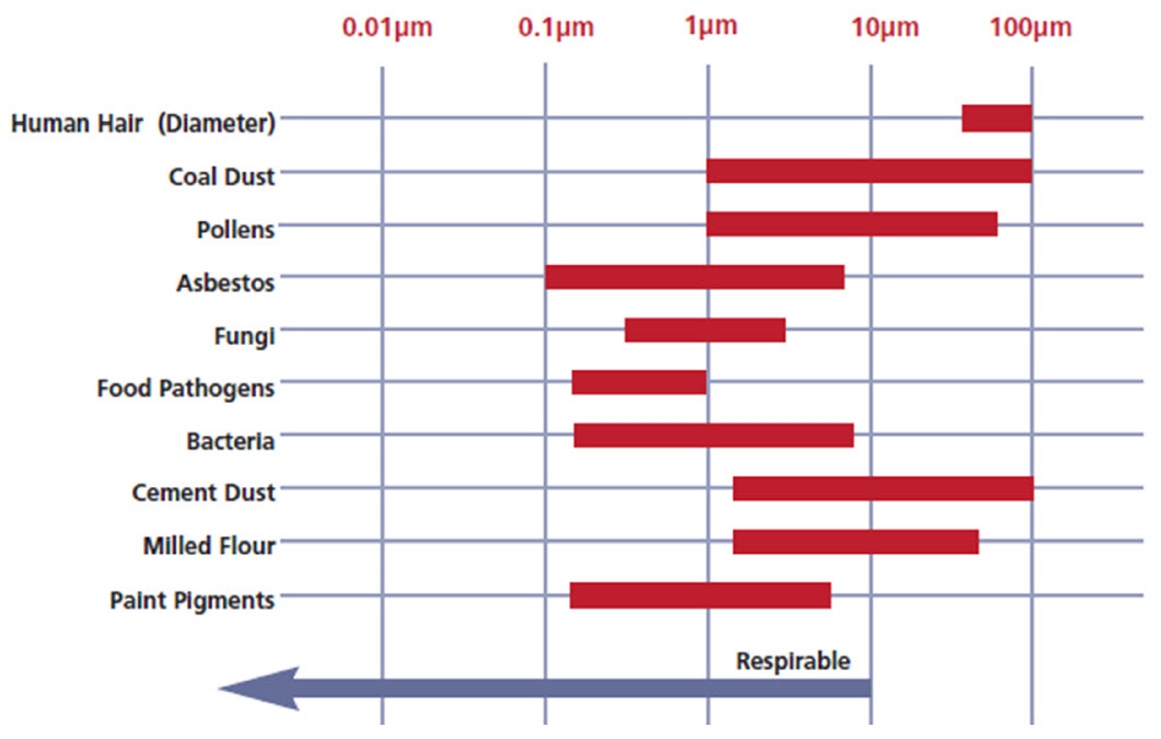
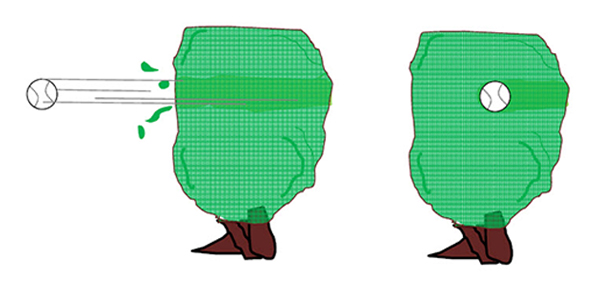
The chart to the right shows the relative sizes of common particles and can be used to help determine if a filter is appropriate for a particular application. Particles or dusts that are smaller than 10 microns are considered “respirable” and are very dangerous. These particles are small enough to reach the air sacks (alveoli) within our lungs and cause serious health issues such as cancer, asthma and asbestosis. Special mechanical filters called critical filters are used to capture submicron particles down to 0.1 microns and are commonly used in vacuums designed to collect hazardous materials. 2. Air SpeedThe speed or velocity of the air in a vacuum system is also an important factor to consider. Air velocity can easily reach several thousand feet/minute in a large vacuum system. Airborne particles will align themselves in the direction of the airflow and the faster particles travel, the deeper they will penetrate in the filter material. To illustrate this point, consider the example bellow of a baseball being thrown into a hedge.
If a baseball is thrown at a high rate of speed, it will penetrate the hedge and come out on the other side. If the baseball is thrown at a slower speed, the branches of the hedge will capture the baseball. This is how a particle acts with a filter.
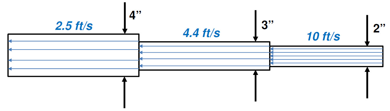
A vacuum cleaner is considered to be a low volume, high velocity air mover. The blades on the turbine are relatively small (so they only push a small volume of air) but the turbine spins very quickly which moves this volume of air at a very high velocity. In contrast, a ceiling fan would be an example of a low velocity, high volume air mover. The blades of the ceiling fan are much larger in comparison and move a larger volume of air. The ceiling fan motor spins relatively slowly so the air moves at a much lower velocity. Always keep in mind that it is the air passing through a vacuum cleaner that does all of the work. The true measure of a vacuum cleaner’s ability to do work is a function of the speed and volume of air that passes through the system. The figure above illustrates how air speed changes with pipe diameter. The blue arrows are “flow lines”. As the diameter of the pipe increases, air speed within the pipe will decrease. The decrease in speed is represented by the wider spacing between the flow lines.
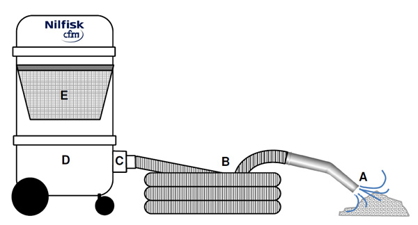
If we apply the principle of air flow to the vacuum system shown, the fastest air will be at points (A) and (B) where the diameter is the smallest. The air speed at the end of the wand (A) must be high enough to lift the dust from the floor. The air speed in the hose must remain high in order to carry the dust all the way back to the collection tank. If the air speed drops too low, dust can settle in the hose. As air passes through the inlet (C) and into the tank (D) the air speed drops dramatically because of the sudden increase in diameter. If you remember the “baseball in the hedge” example, this is exactly what we want. By reducing the air speed, the dust particles slow down making them easier to be captured by the filter (E).
3. Filter Media
Vacuums with larger filters are normally more efficient because there is more area to trap particles and less frequent filter clogging. A small filter will clog quickly due to lack of surface area. A large airflow through a small filter will often cause debris to penetrate the filters. The optimum condition is a slow airflow through a large filter. This allows the particles to be trapped by the filter media. A simple way to increase the surface area of a filter (or reduce it’s ATC) is to use a technique called “pleating”. By pleating or folding the filter material, it is possible to fit a significant amount of surface area into a relatively small space. The filter in the top photo (A) is made by folding a paper media into a cylindrical shape. The spacing between the pleats is critical and affects how the filter will load over time and how easily it can be cleaned. The lower photo (B) shows a heavy duty filter made of polyester cloth. Here, the pleats are sewn together and the spacing between the pleats is controlled by a steel frame on the inside of the filter.
4. Running TimeWhen is a filter most efficient? Over time, debris will build up on the surface of a filter and embed itself into the filter material. This clogging action is known as “blinding” or “loading”. As a filter loads, fewer and fewer particles will be able to penetrate. This causes the filter’s “efficiency” (it’s ability to capture particles) to increase but will cause a decrease in vacuum performance as airflow is reduced. If the filter is not cleaned or replaced, eventually it will become totally blinded, preventing any air or particulate from penetrating. A filter therefore, is actually at its highest efficiency just before it needs to be replaced.
The filter itself (even when new) will create a minor pressure drop in the system. The gauge below shows the approx. pressure loss from a new main filter. As the filter collects dust, the needle will gradually extend further into the green zone. When the needle reaches the beginning of the red zone (position 1), this is an indication that the filter is becoming clogged and will need to be cleaned. At this point, the operator should turn off the vacuum and clean the filter. When the vacuum is turned back on after filter cleaning, the needle should drop further down into the green zone. If the needle reaches the end of the green zone (position 2) and repeated cleaning of the filter does not reduce the pressure, the filter should be replaced. In most cases, the factory installed manometer is only designed to record the pressure loss of the main filter and should only be used as a guide. Adding filters, increasing hose length or decreasing hose diameter can all affect the reading of the manometer and cause it to register in the red zone when the filter is actually clean and in good operating condition. Care should be taken not to overload a vacuum system with too many restrictions. It may be necessary to install a separate manometer for each filter in a vacuum system if the customer wants to be able to monitor each filter independently.
MECHANICAL FILTER EFFICIENCY AND TESTINGNow that we’ve reviewed the four main factors that affect mechanical filtration we can examine how mechanical filters are tested and how two different filters can be compared to each other on the basis of efficiency. Most mechanical filters are designed to capture particles down to a target size (i.e. 1.0, 5.0 or 10 micron). A filter’s ability to capture particles is measured as a percentage. A filter with an efficiency rating of “99.5% @ 1.0 micron” means that the filter will capture and retain 99.5% of all particles 1.0 micron and larger. When stating a filter’s efficiency, you must provide BOTH the particle size and percentage; one without the other is meaningless. Filters are often purchased based on their efficiency rating and this is why it is important to state the efficiency correctly and in terms the customer can understand. A filter with an efficiency rating of only 75% @ 1.0 micron doesn’t make much sense. If 25% of particles 1.0 micron and larger will pass through this filter, the filter would not be considered efficient at the 1.0 micron level. This same filter may be 99.5% efficient at 5.0 micron so it would be better to state the efficiency as 99.5% @ 5.0 microns. This gives the potential customer a clearer picture of the filter’s limitations. It would be safe to assume that this filter’s efficiency at 10.0 micron would be 100%. 1. Penetration Style Testing
There are many different test standards for measuring filter efficiency. Some standards are country specific (Europe, North America) while others are more industry specific (nuclear). Most penetration style testing however, is performed in the same basic manner. A “test smoke” of a specific particle size is generated and passed through a test filter at a specified flow rate. A measuring devices such as a laser particle scanner or photometer is used to count the particles before and after the filter. The filter’s efficiency is based on the percentage of particles that pass through it. This concept is shown to the left. Filters can be compared using several different parameters. If the filtration efficiency of each filter is known, this is generally a good place to start. For the efficiencies listed below, the one on the far right has the highest efficiency. Keep in mind, if the minimum efficiency needed for an application is only 95% @ 2.0 micron; it may be more cost effective to purchase the filter in green. 98% @ 2.0 micron 99.1% @1.5 micron 99.9 % 0.5 micron Using the surface area or ATC ratio of a filter is another good way to compare filters. One filter may have a higher efficiency but a lower ATC ratio or surface area. This could be an expensive filter and with a low ATC ratio it may need to be cleaned or replaced frequently. A filter’s location within a system, it’s cost, shape and materials of construction are all very important to consider when comparing filters. 2. Graduated Filtration
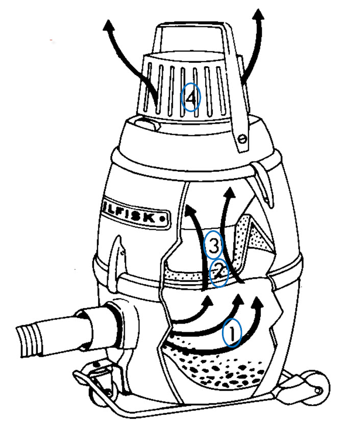
The sketch to the right shows a standard Nilfisk GM80 vacuum with its four stages of filtration. The first stage is a paper dust bag (1) which is used to capture the largest particles entering the vac. The dust bag is a relatively large and inexpensive filter that is meant to be replaced frequently. The efficiency of the dust bag is 99.7% @ 3.0 microns. The second stage of filtration is the main filter (2). This filter is much more substantial and is made of a heavy duty cotton material that resembles felt. The main filter is not meant to be changed very frequently and has a handle on the inside that allows the end user to shake it clean. The efficiency of the main filter is 99.8% @ 3.0 microns. Because the dust bag is a optional filter, the efficiency of the main filter and dust bag are kept very similar. The “micro” filter (3) is the third stage of filtration. As the last stage of filtration before the motor, this filter is meant to capture any fine particles that pass through the main filter that might harm or shorten the life expectancy of the motor. The efficiency of the micro filter is 99.5% @ 2.0 microns. It has very little surface area and is relatively inexpensive to replace. The fourth and final stage of filtration is the HEPA exhaust filter (4). The HEPA filter is used to capture extremely fine and/or harmful particles that are small enough to pass through the first three stages of filtration. The HEPA filter in this case is also used to capture particulate given off by the motor such as carbon brush wear, bearing grease and metal shavings from the motor’s turbine. The efficiency of the HEPA filter is 99.97% @ 0.3 microns. HEPA filters are normally expensive and are not meant to be replaced on a frequent basis. 3. HEPA FiltersThe location of a filter in a vacuum cleaner can play a very important role. In the previous example of the GM80 vacuum, the HEPA filter was used as an exhaust filter. Since this filter was located after the vacuum motor it is referred to as a “downstream” HEPA filter. If the filter were mounted before the motor, it would be an “upstream” HEPA filter. Upstream HEPA filters are commonly used in vacuums that collect hazardous or toxic materials. The upstream HEPA will capture all of the dangerous particles before they make their way into the motor housing which is safer for any technician who may have to service the vacuum in the future. The suction force of the motor constantly pulls against the seal of the upstream HEPA. As the HEPA filter loads, this force will get stronger creating a better seal as times goes on. This is an added design benefit of upstream mounting. The primary use for downstream HEPA filters are in cleanrooms, where the particulate coming off of the motor must be captured to prevent the room from contamination. Some vacuum models can only have an upstream or a downsteam HEPA while some special models can have both. HEPA (and ULPA) filters are sometimes referred to as “critical” or “absolute” filters because of their ability to capture dangerous, submicron sized particulate. Specific standards and test methods have been developed over the past several decades for testing this special class of filters.
For more than 30 years, the test used for critical filters in the US was simply referred to as the “DOP” test. In recent years, the methods and practices outlined in the DOP test have been scrutinized by the international community which has lead to the creation of several new test standards. To be competitive in the global market today, many manufacturers of critical filters are now providing individual certificates for their filters to provide verification that the filters have been manufactured and tested to the appropriate standards. If you consider that critical filters like HEPA/ULPAs are being used every day around the world to capture materials like asbestos, lead, arsenic, mold and radioactive dust, it’s no wonder why this level of testing and certification is needed.
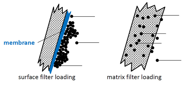
TYPES OF MECHANICAL FILTERSThere are many different shapes and kinds of mechanical filters. In this section we will explore the most popular mechanical filters used in vacuum cleaners today. The names of many of these filters come from their functional use or shape and may differ depending upon which industry you are working in. There are two main types of mechanical filters, surface and matrix. Surface filters capture and retain particles only on their outer surface. These types of filters are often coated with a “membrane“ material that prevents the particles from penetrating deep into the filter material. The goal is to have the particles stick to each other and not to the filter; the term for this is “caking”. Teflon (PTFE) and PVC are two popular materials used as membranes. Surface filters are normally used when collecting fine, sticky powders like protein or sugar. Since only the outer surface of the filter is being used, surface filters tend to blind more quickly but they are much easier to clean (this is the trade off). These filters are usually more expensive than standard filters and are commonly offered as an upgrade. Surface filters should not be used to collect sharp or abrasive particles as these will wear away the expensive membrane coating on the surface filter.
Filter Styles
Dust bags are not considered surface or matrix style because all of the particles are collected in the internal cavity of the bag itself.
• A prefilter is a general term for a filter that is used to protect another filter. In the example above, the dust bag could be considered a prefilter for the sack filter. The photo to the right shows a simple polyester sleeve. This sleeve slides over another filter and is used to prolong the life of the filter it covers. Prefilters are a simple way to enhance the efficiency of an existing filter. They are normally inexpensive and disposable and can be either surface or matrix style. • Nilfisk-CFM uses main filters made of different materials for use in specific applications. Flame resistant (Nomex) filters are used for high heat, antistatic filters are used in explosive environments and membrane filters are used for fine, sticky powders. Polypropylene adds chemical resistance while polyurethane help resists abrasion.
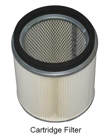
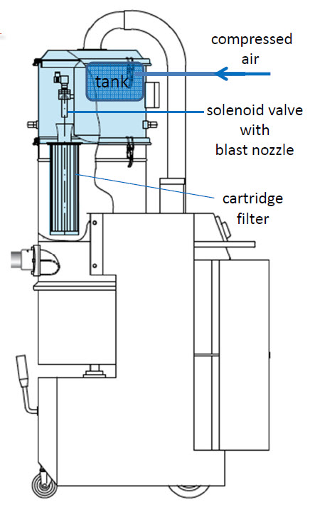
The image to the left shows an industrial vacuum cleaner that has been outfitted with a fully automatic reverse purging cartridge filter system. Compressed air is supplied to a reservoir tank at the top. Solenoid valves positioned directly above the cartridge filters open at adjustable time intervals and direct the compressed air down inside the cartridge filter. The blast of air knocks loose dust particles from the filter. The particles fall down into the collection container and the entire process repeats itself.
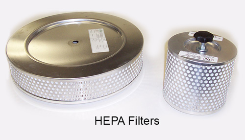
• HEPA/ULPA filters come in all sorts of sizes and shapes. The filter media (paper) in each filter is surrounded by a metal or plastic framework. This is necessary because the filter media used in HEPA and ULPA filters is extremely delicate. The slightest tear or hole will cause the HEPA/ULPA filter to fail a penetration test. Each filter has an information label attached directly on the outside.
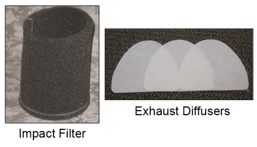
• Exhaust diffusers are the last stage of filtration in a vacuum and have a variety of different uses. They can be used to capture particulate emitted by the motor or dampen the noise level of the vacuum by reducing the speed of the exhaust air. In some cases, they provide a simple barrier to prevent foreign objects from falling down inside the motor or turbine cavity.
|
.jpg)
.jpg) Filtering efficiency is affected by the relationship of the surface area of the filter media to the volume of air trying to pass through it. This relationship is known as the “air to cloth” ratio (ATC). The lower the ATC ratio, the more efficient the filtering system. Likewise, the higher the ATC ratio, the less efficient the filtering system. For example, if a vacuum has 25 ft2 of main filter and an airflow of 250 cfm, the ATC ratio will be 10 to 1. Another vacuum, having only 20 ft2 of main filter and an airflow of 300 cfm, would have an ATC ratio of 15 to 1.
Filtering efficiency is affected by the relationship of the surface area of the filter media to the volume of air trying to pass through it. This relationship is known as the “air to cloth” ratio (ATC). The lower the ATC ratio, the more efficient the filtering system. Likewise, the higher the ATC ratio, the less efficient the filtering system. For example, if a vacuum has 25 ft2 of main filter and an airflow of 250 cfm, the ATC ratio will be 10 to 1. Another vacuum, having only 20 ft2 of main filter and an airflow of 300 cfm, would have an ATC ratio of 15 to 1.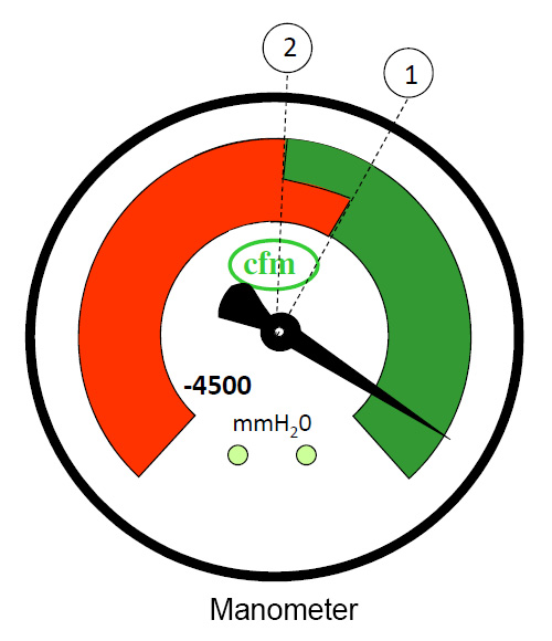 Devices such as differential pressure gauges or manometers are often used on industrial strength vacuums to monitor filter performance. The gauges measure the difference in air pressure between the outside (ambient) air and the air on the inside (clean side) of the filter. As a filter begins to load, air will have more difficulty passing through it and this will register on the gauge as a “pressure drop”.
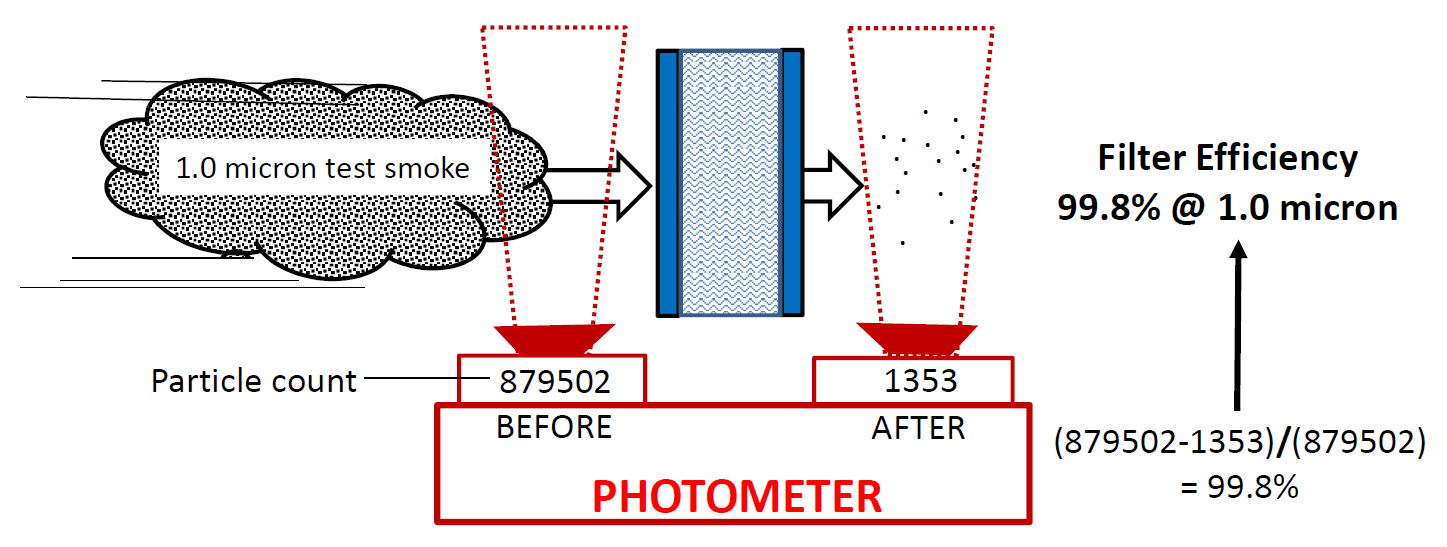
 Matrix (or depth) filters
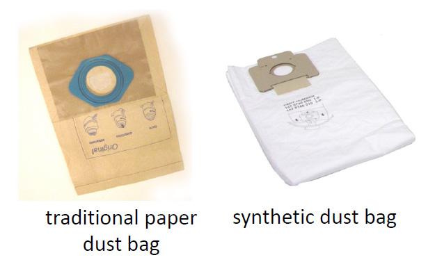 • Dust bags
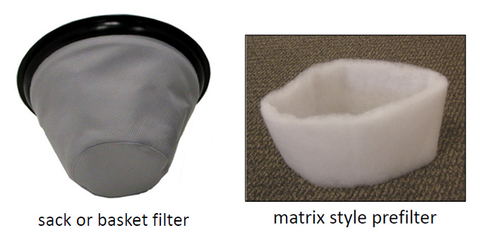 • Sack (or basket) filters
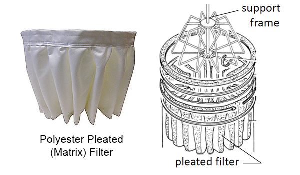
 •
• 
 •
•